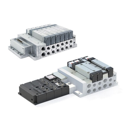
Valve islands, Size 5, Multipole and Fieldbus Series D5
Fieldbus connection with the most common communication protocols PROFIBUS-DP, PROFINET, CANopen, EtherNET/IP, EtherCAT and IO-Link.
Multipole connection with 25 or 44 pins
Valve functions: 2×3/2; 5/2; 5/3 CC, CO, CP
Multipole connection with 25 or 44 pins
Valve functions: 2×3/2; 5/2; 5/3 CC, CO, CP
In this configuration, Series D1 and D2 valves (size 10 and 16 mm) can be combined into one unique Island. Some benefits of this version are the small dimensions, only one Multipole or Serial connection point, easy installation and the possibility to have different flow rates.
All size D2 components of this configuration remain unvaried, while for size D1 a longer subbase is used.
All electric and pneumatic components and characteristics of the single versions remain unvaried.
The COILVISION function is included also in this version.
Categories: CAMOZZI, Fieldbus and Multipoles systems, Valve islands
General Data
| PNEUMATIC SECTION | |
| Valve construction | Spool with seals |
| Valve functions | 5/2 monostable and bistable 5/3 CC, CO, CP 2×3/2 NC 2×3/2 NO 1×3/2 NC 1×3/2 NO |
| Materials | spool: AL spool seals: HNBR other seals: NBR body: AL end caps: polymer individual subbase: AL |
| Connections | Inlet 2 and 4: threaded G 3/8 Supply 1: threaded G 1/2 Exhaust 3 and 5: G 1/2 |
| Temperature [°C] | 0 ÷ 50°C |
| Air characteristics | Compressed, filtered and non-lubricated air in class [7:4:4] according to ISO 8573-1:2010. In case lubrication should be necessary, only use oils with a maximum viscosity of 32 Cst and the version with external servo-pilot supply. The air quality of the servo-pilot supply must be of class [7:4:4] according to ISO 8573-1:2010 (do not lubricate). |
| Valve sizes | 4 = 25 mm |
| Operating pressure | -0,9 ÷ 10 bar (-0.7 ÷ 10 bar for 2×3/2 versions) |
| Pilot pressure [bar] | 2.5 ÷ 7 bar |
| External pilot pressure | 4,5 ÷ 7 bar (with operating pressure exceeding 6 bar for the version 2×3/2) |
| Flow rate | 2000 Nl/min |
| Mounting position | Any position |
| Protection class | IP65 |
| ELECTRICAL SECTION MULTIPOLE VERSION | |
| Sub-D connector | 25 or 44 pins |
| Max. absorption | 0.8 A (with Sub-D connector 25 pins) 1,5 A (with Sub-D connector 44 pins) |
| Supply voltage | 24 V DC +/- 10% |
| Max. number of coils to operate | 22 on 11 valve positions (with Sub-D connector 25 pins) 38 on 19 valve positions (with Sub-D connector 44 pins) |
| Signalling LED | Multipole: green LED – presence of power red LED – anomaly Valve: yellow LED – presence of power blinking yellow LED – operating fault |
| ELCTRICAL SECTION FIELDBUS VERSION | |
| General data | See Multi-serial Modules section on the next pages |
| Max. absorption | 2.5 A |
| Supply voltage [Vdc] | 24 V DC +/-10% logic supply 24 V DC +/-10% power supply |
| Max. number of coils to operate | 128 on 64 valve positions |
| Max. number of digital inputs | 128 |
| Max. number of analog inputs | 16 |
| Max. number of digital outputs | 128 |
| Max. number of analog outputs | 16 |
| IO-LINK version | |
| Max n° of coils to operate | 64 on 32 valve positions |
| Input and Output | No |
| Type of port | Class B |
| IODD Configuration file (The IO-Link module on the valve island is auto-configured to operate with the right IODD) | Up to 12, 24 or 32 valve positions per island |
Download
Certifications