Multi-serial Module Series CX4
Interface with: PROFIBUS, CANopen, EtherNet/IP, PROFINET, EtherCAT.
Can be integrated with I/O Modules.
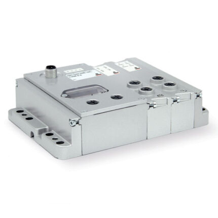
Series CX4 multi-serial module can interface with the most common fieldbus protocols, like Profibus-DP, CANOpen, EtherCAT, EtherNet/IP, PROFINET. The possibility to enlarge with both Digital and Analog I/O modules, the acquisition of signals coming from Bridge, RTD or TC sensors, the resolution of up to 24 bit and the high number of manageable signals make it particularly suitable for different needs.
Connectable with PC through MicroUSB port, check and configuration of connected components by means of UVIX software. Configuration through Fieldbus. By means of a mechanical interface connection it is used in combination with the Series D valve islands.
Categories: CAMOZZI, Fieldbus and Multipoles systems, Multi-serial modules
General Data
| Number of digital outputs | 128 |
| Number of analogic outputs | 16 |
| Number of digital inputs | 128 |
| Number of analogic inputs | 16 |
| Max. input absorption | 1,5 A |
| Max. output absorption | 2,5 A |
| Supply voltage | 24 V DC +/-10% logic supply 24 V DC +/-10% power supply |
| Protection | overload and reverse polarity |
| Protection class | IP65 (IP20 in case of module I/O with terminal block) |
| Conform with standards | EN-61131-2 |
| Operating temperature | 0-50°C |
| Material | polymer |
Coding Example
| CX | 4 | 01 | W | – | 2A2Q | – | R |
| CX | SERIES |
| 4 | VERSION 4 = CX4 |
| 01 | PROTOCOL 00 = Base closed without Fieldbus cover 01 = PROFIBUS 03 = CANopen 04 = EtherNet/IP 05 = EtherCAT 06 = PROFINET |
| W | INTERFACE 0 = No interface W = WLAN |
| 2A2Q | INPUT/OUTPUT MODULES 0 = no module A = 8 digital inputs M8 B = 16 digital inputs terminal block (Push-in) connection C = 2 analog inputs (config. 0-10V, ±10V, 0-20mA, 4-20mA, ±20mA) M12 D = 2 analog inputs (config. 0-10V, ±10V, 0-20mA, 4-20mA, ±20mA) terminal block (Push-in) connection E = 2 BRIDGE inputs M12 F = 2 BRIDGE inputs terminal block (Push-in) connection G = 2 RTD inputs M12 (PT100, PT200, PT500, PT1000) H = 2 RTD inputs terminal block (Push-in) connection (PT100, PT200, PT500, PT1000) L = 2 TCM12 inputs (THERMOCOUPLES) M = 2 TC inputs terminal block (Push-in) connection (THERMOCOUPLES) Q = 8 digital outputs M8 R = 16 digital outputs terminal block (Push-in) connection S = subnet expansion T = 2 Analog outputs (config. 0-10V,±10V,0-20mA, 4-20mA,±20mA), M12 U = 2 Analog outputs (config. 0-10V,±10V,0-20mA,4-20mA,±20mA), terminal block P = 8 digital inputs (4 M12 connectors) Y = 8 digital outputs (4 M12 connectors) W ** = Closed base without I / O cover |
| R | FIXING TYPE = direct R = DIN rail |
** = The closed base without I / O cover must always be placed after the other modules if present ex: CX401W-2A2W-R…
Download
Instruction sheets
