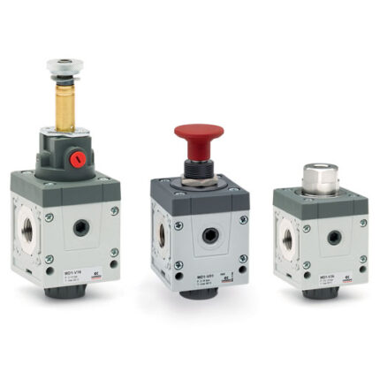
Manual isolation valves are ideal to allow an easy access to the FRL group.
The system is depressurized with the de-activation of the valve.
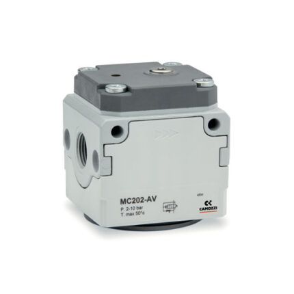
Electropneumatic isolation valves: ideal where manual access is difficult, they allow a maximum positioning flexibility and are designed to pressurize or depressurize pneumatic systems.
The built-in manual override guarantees security in case of an emergency.
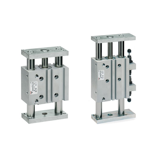
The Series MX has been realized to offer a multi-sector solution that guarantees saving in terms of installation time, space and costs.