| 63 | SERIES | |
| M | VERSION
M = standard, magnetic
V = uniform movement (no stick slip), magnetic
L = low friction, magnetic | |
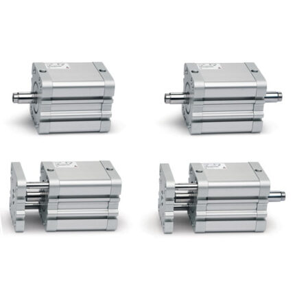
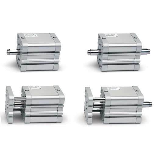
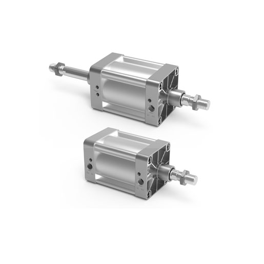
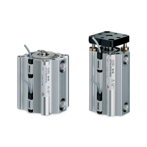
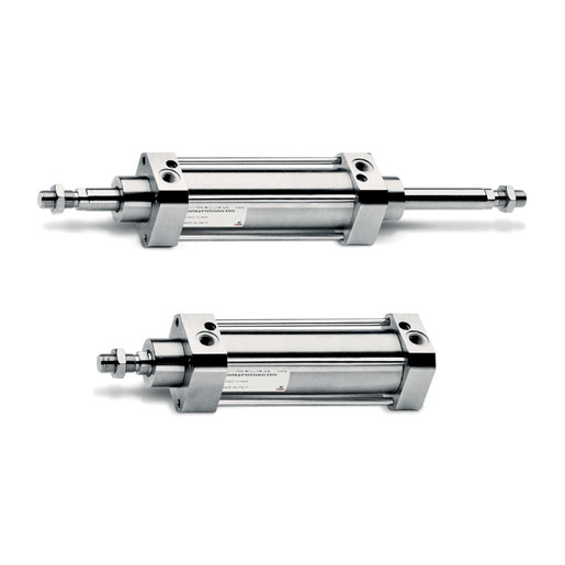
| P | CONSTRUCTION
T = round tube
P = profile | |
| 2 | OPERATION
1 = single-acting, front spring
2 = double-acting
6 = double-acting, through-rod
7 = single-acting, through-rod
9 = single-acting, rear spring | PNEUMATIC SYMBOLS
CS07/CS18
CD08 – CD09 – CD10 – CD11
CD13
CS11
CS14/CS17 |
| C | CUSHIONING
N = no cushioning (mechanical endstops)
C = cushioning on both sides
F = front cushioning
R = rear cushioning | PNEUMATIC SYMBOLS
CD08
CD09/CD13
CD11
CD10 |
| 050 | BORE
032 = 32 mm
040 = 40 mm
050 = 50 mm
063 = 63 mm | 080 = 80 mm
100 = 100 mm
125 = 125 mm |
| A | CONSTRUCTIVE TYPE
A = standard with rod nut
RL = cylinder with rod lock | DC = back to back cylinder with DC accessory [X1/X2]
TR = back to back cylinder for round tube [X1/X2]
F = cylinder with centre trunnion |
| 0200 | STROKE
= standard
N = tandem
/ = more positions X1/X2 [X1<X2] | |
| W | TEMPERATURE RANGE
= standard (-20°/+80°)
W = high temperatures (150°C) | Z = low temperatures (-40°C)
Y = low temperatures (-50°C) |
| RESISTANCE TO CORROSION
= standard
C1 = rod nut AISI 304 stainless steel, rod AISI 304 stainless steel
C2 = end cap treated screws (profile) or AISI 303 tie-rods
and AISI 420B tie-rods (round tube) | C3 = C2 + AISI 316 rod nut, AISI 316 rod
C4 = C1 + C2
C5 = C3 + end caps with triple protection |
| ROD VARIATIONS
= standard (male rod thread)
F = female rod thread
K = end caps with Kanigen treatment (only for corrosion resistance category C2, C3 and C4)
L = without rod seal (rear air inlet only)*
V = FKM rod seal
R = NBR rod seal
U = unlubricated operation | H = hydrolytic environment
A = use in food and other frequent washdown applications
G = dry and dusty environments (with brass rod scraper
and chrome-plated stainless steel AISI 420B rod)
B = cylinder with NBR bellow rod protection
(_ _ _) = extended rod _ _ _ mm |
| OTHER
P = cylinder with RAL 7035 polyurethane coating | |
| CERTIFICATIONS
EX = ATEX | |