Flow control valves Series PSCU, PMCU, PSVU, PMVU, PSCO, PMCO
Unidirectional and bidirectional flow regulators with banjo in brass (M5) or in technopolymer (G1/8, G1/4, G3/8)
Ports: M5, G1/8, G1/4, G3/8
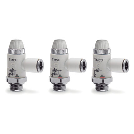
These unidirectional and bidirectional flow controllers have been designed as small as possible so as to be mounted directly on valves or cylinders.
The great variety of adjustable fittings makes it possible to complete the regulator with the most suitable system in relation to the available tube.
All models are supplied complete with banjo flow controllers.
Categories: CAMOZZI, Flow control valves, Valves and Solenoid valves
General Data
| Construction | Needle type |
| Valve group | Unidirectional and bidirectional controller |
| Materials | Body, regulation screw: stainless steel (M5), brass (G1/8 – G1/4 – G3/8) Collet and insert = brass Banjo: brass (M5), technopolymer (G1/8 – G1/4 – G3/8) Controller = technopolymer – seals = NBR |
| Mounting | By male thread |
| Ports | M5 – G1/8 – G1/4 – G3/8 |
| Installation | In any position |
| Operating temperature | 0°C ÷ 60°C (with dry air -20°C) |
| Operating pressure | 1 ÷ 10 bar |
| Nominal pressure | 6 bar |
| Nominal flow | See graph |
| Nominal diameter Ø [mm] | M5 = 1,5 mm – G1/8 = 2 mm – G1/4 = 4 mm – G3/8 = 7 mm |
| Fluid | Filtered air If lubricated air is used, it is recommended to use ISOVG 32 oil. Once applied the lubrication should never be interrupted. |
Coding Example
| P | M | CU | 7 | 04 | – | 1/8 | – | 4 |
| P | SERIES |
| M | ACTUATION M = Manual S = Screwdriver |
| CU | ASSEMBLY CU = On cylinders unidirectional VU = On valves unidirectional CO = Bidirectional |
| 7 | VERSIONS 6 = Needle (screwdriver operated) 7 = Needle (manual operated) |
| 04 | NOMINAL DIAMETER 02 = Ø1,5 MAX 04 = Ø2 MAX 06 = Ø4 MAX 08 = Ø7 MAX |
| 1/8 | PORTS M5 = M5 1/8 = G1/8 1/4 = G1/4 3/8 = G3/8 |
| 4 | TUBE 4 = Ø4 6 = Ø6 8 = Ø8 10 = Ø10 12 = Ø12 |
To ensure the right choice of unidirectional flow controller, proceed as follows: calculate the quantity of air in Nl/min (see cylinders table); determine the stroke time of the cylinder; refer to graph to see which is the right type of controller.
