Valves and solenoid valves Series D VB version
2×3/2; 5/2; 5/3-way
Manifold assembly
Size 10,5 – 16 – 25 mm
Manifold assembly
Size 10,5 – 16 – 25 mm
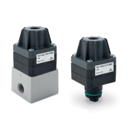
Camozzi has developed a new series of valves for applications with limited installation space where it is necessary to have the control elements as close to the actuator as possible.
Thanks to the extreme robust aluminium body, the Series D valves guarantee maximum reliability even under difficult operating conditions.
Thanks to the extreme robust aluminium body, the Series D valves guarantee maximum reliability even under difficult operating conditions.
General Data
| Valve construction | Spool- type |
| Valve functions | 2×3/2 NC/NO/NC+NO; 5/2; 5/3 CC/CO/CP |
| Materials | Body, spool, bases = AL; end caps = technopolymer; seals = HNBR |
| Environmental temperature | 0°C ÷ 50° C |
| Medium | Compressed, filtered and non-lubricated air in class [7:4:4] according to ISO 8573-1:2010. In case lubrication should be necessary, only use oils with a maximum viscosity of 32 Cst and the version with external servo pilot. The air quality for the servo pilot should be of class [7:4:4] according to ISO 8573-1:2010. |
| Voltage | 24V DC |
| Voltage tolerance | ± 10% |
| Power consumption | 1W |
| Class of insulation | Class F |
| Protection class | IP65 with EN 175301 C connector (“3” actuation. Ex DIN 43650)* IP65 with M8 connector (“C” actuation)* IP40 with micro connector (“E” actuation)* |
* See coding example.
Coding Example
| D | 1 | E | VB | – | B | P |
| D | SERIES |
| 1 | SIZE 1 = 10,5 mm 2 = 16 mm 4 = 25 mm |
| E | ACTUATION E = Electric (D1 and D2) 3 = Electric 15 mm (D2 and D4) C = Electric with M8 connections (D1 and D2) |
| VB | COMPONENT VB = Valve with body for sub-base |
| B | TYPE OF SOLENOID VALVE M = 5/2 Monostable B = 5/2 Bistable C = 2 x 3/2 NC A = 2 x 3/2 NO G = 2 x 3/2 (NC+NO) N = 5/3 CP V = 5/3 CC K = 5/3 CO |
| P | TYPE OF MANUAL OVERRIDE P = Push button (not for D4) R = With push and turn device |
| VERSION 3, through the connector with rectifier bridge 125-571-3, can be used for AC applications (see the connectors at the end of the section) |
Coding Example
| DC | B | 1 | 0 | – | 12 |
| DC | SERIES |
| B | MANIFOLD B = For type VB solenoid valves |
| 1 | SIZE 1 = 10,5 mm 2 = 16 mm 4 = 25 mm |
| 0 | SERVO-PILOT 0 = Kit included for internal/external servo-pilot supply |
| 12 | N° OF POSITIONS 2 3 4 … 16 |
Coding Example Manifold with solenoid valves and fittings
| DC | B | 1 | E | R | A | – | MBMXCVB | – | 3BX2AB | – | CSL | – | R |
| DC | SERIES | ||
| B | MANIFOLD WITH SOLENOID VALVES B = For type VB solenoid valve | ||
| 1 | SIZE 1 = 10,5 mm 2 = 16 mm 4 = 25 mm | ||
| E | ACTUATION E = Electric (D1 and D2) 3 = Electric 15 mm (D2 and D4) C = Electric with M8 connector (D1 and D2) | ||
| R | TYPE OF MANUAL OVERRIDE P = Push button (not for 3 actuation) R = With push and turn device | ||
| A | SERVO-PILOT SUPPLY A = Internal B = External | ||
| MBMXCVB | TYPE OF SOLENOID VALVE M = 5/2 Monostable B = 5/2 Bistable C = 2 x 3/2 NC A = 2 x 3/2 NO G = 2 x 3/2 (NC + NO) V = 5/3 CC K = 5/3 CO N = 5/3 CP L = Free position X = Additional supply and exhaust Y = Additional supply and exhaust with silencer | ||
| 3BX2AB | CONNECTIONS ON VALVE POSITIONS (OUTLETS 2 AND 4 ON MANIFOLD) T = Thread A = Ø4 (D1) Fittings 6512 4-M7-M B = Ø6 (D1) Fittings 6512 6-M7-M; (D2) S6510 6-1/4 C = Ø8 (D2) Fittings S6510 8-1/4 D = Ø10 (D2) Fittings 6512 10 1/4-M; (D4) S6510 10-3/8 E = Ø12 (D4) Fittings S6510 12-3/8 F = Ø14 (D4) Fittings S6510 14-3/8 L = Free position X = Threaded plate Y = See codes D1AVB-Y / D2AVB-Y / D4AVB-Y | ||
| CSL | MANIFOLD CONNECTIONS (supply and exhausts) T = Thread (on both sides) C = Fittings Ø8 on connections 1;3;5 CS = Fittings Ø8 on supply + silencers on exhausts D = Fittings Ø10 on connections 1;3;5 DS = Fittings Ø10 on supply + silencers on exhausts E = Fittings Ø12 on connections 1;3;5 ES = Fittings Ø12 on supply + silencers on exhausts F = Fittings Ø14 on connections 1;3;5 FS = Fittings Ø14 on supply + silencers on exhausts G = Fittings Ø16 on connections 1;3;5 GS = Fittings Ø16 on supply + silencers on exhausts CONNECTION SIDE Servo-pilot fittings: | (D1) 6512 8-1/8-M (D1) 6512 8-1/8-M + 2921 1/8 (D2) S6510 10-3/8 (D2) S6510 10-3/8 + 2921 3/8 (D2) S6510 12-3/8 (D2) S6510 12-3/8 + 2921 3/8 (D2) S6510 14-3/8 (D2) S6510 14-3/8 + 2921 3/8 (D4) S6510 16-1/2 (D4) S6510 16-1/2 + 2921 1/2 | (D2) S6510 8-3/8 (D2) S6510 8-3/8 + 2921 3/8 (D4) S6510 10-1/2 (D4) S6510 10-1/2 + 2921 1/2 (D4) S6510 12-1/2 (D4) S6510 12-1/2 + 2921 1/2 (D4) S6510 14-1/2 (D4) S6510 14-1/2 + 2921 1/2 |
| R | FIXING = Direct R = Port for DIN rail | ||
| VERSION 3, through the connector with rectifier bridge, can be used for AC applications (see the connectors at the end of the section). |
Download
Certifications