Media separated solenoid valves Series PDV
2/2-way – Normally Closed (NC)
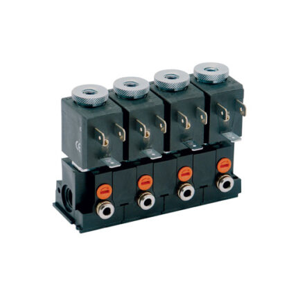
Series PDV directly operated solenoid valve is available with several nominal diameters and in three different versions according to the electrical connection.
Moreover, the fluid separation membrane protects the medium from extreme changes of temperature due to heating of the solenoid.
To choose the most suitable model for a specific application, check the chemical compatibility of the medium with the available materials of body and seals.
General Data
| TECHNICAL FEATURES | |
| Function | 2/2 NC |
| Operation | Direct acting with fluid separation membrane |
| Pneumatic connection | On subbase |
| Orifice diameter | 0.8 … 2 mm |
| Flow coefficient kv (l/min) | 0.25 … 0.8 |
| Operating pressure | 0 … 7 bar |
| Operating temperature | 10 ÷ 50 °C (FKM/EPDM) / 20 ÷ 50 °C (FFKM) |
| Fluid | Inert or corrosive liquids and gases compatible with the materials in contact |
| Response time when discharging (ISO 12238) | ≤ 15 ms |
| Installation | In any position |
| MATERIALS IN CONTACT WITH THE MEDIUM | |
| Body | PEEK |
| Seals | FKM – EPDM – FFKM |
| ELECTRICAL FEATURES | |
| Voltage | 12 … 24 V DC – other voltages on demand |
| Voltage tolerance | ±10% |
| Power consumption | 2 W |
| Duty cycle | ED 100% |
| Electrical connection | Industrial standard (9.4 mm), DIN EN 175 301-803-C (8 mm), 300 mm flying leads |
| Protection class | IP65 with connector |
Special versions available on request.
Coding ExampleDownload
| PDV | C0 | 1 | 22 | – | B7 | 3 | G | N | – | M | 00 | 4A | C023 |
| PDV | SERIES | |
| C0 | BODY DESIGN C0 = Body with interface for subbase | |
| 1 | NUMBER OF WAYS – FUNCTIONS 1 = 2/2-way – NC | |
| 22 | PNEUMATIC CONNECTIONS 22 = PDV-type interface, 2-way | |
| B7 | ORIFICE DIAMETER A7 = Ø 0.8 mm B3 = Ø 1.2 mm B7 = Ø 1.6 mm C1 = Ø 2.0 mm | |
| 3 | SEAL MATERIAL 3 = FKM 4 = EPDM 5 = FFKM | |
| G | BODY MATERIAL G = PEEK | |
| N | MANUAL OVERRIDE N = Not foreseen | |
| M | FIXING M = Fixing screws for metal | |
| 00 | OPTIONS 00 = None | |
| 4A | ELECTRICAL CONNECTION 3A = DIN EN 175 301-803-C (8 mm) 4A = Industrial standard (9.4 mm) 7A = 300 mm flying leads |
3C = DIN EN 175 301-803-C (8 mm) with coil rotated 180° 4C = Industrial standard (9.4 mm) with coil rotated 180° 7C = 300 mm flying leads with coil rotated 180° |
| C023 | VOLTAGE – POWER CONSUMPTION C020 = 12 V DC – 2 W C023 = 24 V DC – 2 W | |
| OPTIONS = Standard OX2 = For oxygen (non-volatile residue less than 33 mg / m2) |
