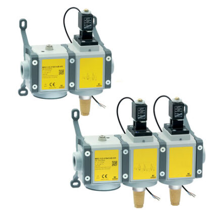
3/2-way quick exhaust safety valves Series MX SAFEMAX
Ports: G1/2
Series MX SAFEMAX solenoid valves are equipped with an integrated sensor that detects the position of the spool and enables to quickly exhaust the system in case of emergency. The sensor is in ON state (closed contact) with the valve in closing position, system exhaust. The single channel valve is classified in category 2 and can reach Performance level D. The double channel valve is classified in category 4 and can reach Performance level E.
Please note: the safety valve is not sufficient, alone, to guarantee the safety function. Its setup requires the use of a monitoring device.The Machinery Directive (MD) 2006/42 / EC establishes the safety requirements that a machine must respect in order to protect the health of people during its use. Series MX SAFEMAX solenoid valves comply with ISO 13849-1, regarding the safe design of control systems that perform safety functions.
Please note: the safety valve is not sufficient, alone, to guarantee the safety function. Its setup requires the use of a monitoring device.The Machinery Directive (MD) 2006/42 / EC establishes the safety requirements that a machine must respect in order to protect the health of people during its use. Series MX SAFEMAX solenoid valves comply with ISO 13849-1, regarding the safe design of control systems that perform safety functions.
Categories: Air treatment, CAMOZZI, Safety valves
General Data
| Construction | Modular, compact, spool-type |
| Ports | G1/2 |
| Mounting | In-line, wall-mounting (by means of clamps) |
| Working temperature | -5 ÷ +60 °C |
| Working pressure | With internal servo-pilot: 3,5 bar ÷ 10 bar With external servo-pilot: 0,5 bar ÷ 10 bar (pilot 3,5 bar ÷ 10 bar, greater or equal to working P) |
| Flow rate (6 bar) | Single version: 1→2 = 5600 Nl/min (ΔP 1) 2→3 = 5000 Nl/min (free flow) Double version: 1→2 = 4100 Nl/min (ΔP 1) 2→3 = 5000 Nl/min (free flow) |
| Medium | Filtered air in class [7:4:4] according to ISO 8573-1 In case lubricated air is used, we recommend ISOVG32 oil and to never interrupt lubrication |
| COIL SPECIFICATIONS | |
| Connection | DIN EN 175 301-803-B |
| Voltage | 24V DC (±10%) 3,1W (ED 100%) |
| SENSOR SPECIFICATIONS | |
| Connection | With wires, M8 |
| Voltage | 10-28V DC |
| Operation | Magnetoresistive |
| Contact | N.O. PNP, ON signal with sol. valve in NC position |
| Max current | EX version: 200 mA 0,65 W UL version: 100 mA 3 W CE version: 200 mA 5,5 W |
| COMPLIANCE WITH EN ISO 13849-1 STANDARD | |
| Performance level reachable (PL) | Single version: category 2, PLd Double version: category 4, PLe |
| B10d | 2.000.000 cycles |
Coding Example
| MX | 2 | – | 1/2 | – | V | 16 | 2 | 0 | A | B | – | KK | – | LH |
| MX | SERIES |
| 2 | SIZE |
| 1/2 | PORT 1/2 = G1/2 |
| V | COMPONENT V = 3/2-way valve |
| 16 | CONSTRUCTION 16 = Internal servo-pilot 17 = External servo-pilot |
| 2 | CHANNEL 2 = Single |
| 0 | ACCESSORIES 0 = Without silencer 1 = With silencer |
| A | SENSOR A = UL sensor, 2 mt cable B = UL sensor, 5 mt cable C = ATEX sensor, 2 mt cable D = ATEX sensor, 5 mt cable E = CE sensor M8 connector, 300 mm cable |
| B | VERSION A = Atex B = UL C = CE Sensor and version must comply with the same Standard / directive AB, BB – CA, DA – EC |
| KK | MOUNTING = Without mounting accessories HH = Side quick clamps and flanges JJ= Side wall clamps and flanges KK = Side wall brackets and flanges |
| LH | FLOW DIRECTION = From left to right (standard) LH = From right to left |
Coding Example double valve
| MX | 2 | – | 1/2 | – | V | 16 | 4 | 0 | A | B | – | KK | – | LH |
| MX | SERIES |
| 2 | SIZE |
| 1/2 | PORT 1/2 = G1/2 |
| V | COMPONENT V = 3/2-way valve |
| 16 | CONSTRUCTION 16 = Internal servo-pilot 17 = External servo-pilot |
| 4 | CHANNEL 4 = Double |
| 0 | ACCESSORIES 0 = Without silencer 1 = With silencer |
| A | SENSOR A = UL sensor, 2 mt cable B = UL sensor, 5 mt cable C = ATEX sensor, 2 mt cable D = ATEX sensor, 5 mt cable E = CE sensor M8 connector, 300 mm cable |
| B | VERSION A = Atex B = UL C = CE Sensor and version must comply with the same Standard / directive AB, BB – CA, DA – EC |
| KK | MOUNTING = Without mounting accessories Z = Central wall clamp Y= Central wall bracket HH = Side quick clamps and flanges JJ= Side wall clamps and flanges KK = Side wall brackets and flanges |
| LH | FLOW DIRECTION = From left to right (standard) LH = From right to left |