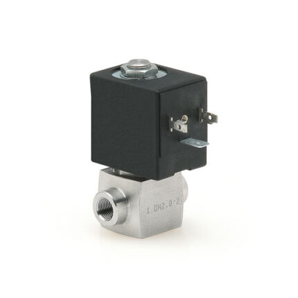
Solenoid valves Series CFB
2/2-way – Normally Closed (NC) and Normally Open (NO)
3/2-way – Normally Closed (NC)
Series CFB solenoid valves for general purpose are available in the NC and NO version, 2/2 and 3/2-way.
Special versions are available on demand for the protection against the water hammer or with specific traitments for the interception of aggressive fluids.The valve function is determined by a poppet or by a diaphragm with operation direct or indirect.
Different versions are available according to the nominal diameter and to the threaded ports, as shown in the following tables.
They can thus satisfy various requirements in terms of flow rates and working pressures.
General Data
| TECHNICAL FEATURES | |
| Function | 2/2 NC – 2/2 NO – 3/2 NC |
| Operation | Direct acting poppet type – servo-assisted with diaphragm |
| Pneumatic connections | G1/8 … G2 threads |
| Orifice diameter | 1.4 … 50 mm |
| Flow coefficient kv (l/min) | 0.14 … 45 |
| Operating pressure | 0 ÷ 0.8 … 22 bar |
| Operating temperature | -10 ÷ 90 … 140 °C |
| Fluid | Air, water, liquid and gaseous fluids with max viscosity 37 cSt (5° E) |
| Response time | ON <15 ms – OFF <25 ms |
| Installation | In any position |
| MATERIALS IN CONTACT WITH THE MEDIUM | |
| Body | Brass (alimentary or anti-limestone nickel-platings on demand) |
| Seals | NBR (CFB-A, CFB-E) – FKM (CFB-B, CFB-D) – EPDM (on demand) |
| Internal parts | Stainless steel – stainless steel and brass (CFB-D1) |
| ELECTRICAL FEATURES | |
| Voltage | 12 V DC, 24 V DC – 24 V 50 Hz, 110 V 50/60 Hz, 220/230 V 50/60 Hz |
| Voltage tolerance | ±5% (DC) – ±10% (AC) |
| Power consumption | 10 … 30 W (DC) – 9 … 29 VA (AC) |
| Duty cycle | ED 100% |
| Insulation class | H (180°C) |
| Electrical connection | Industry standard form B – DIN EN 175 301-803-A |
| Protection class | IP65 with connector |
Special versions available on demand.
It is recommended to use connections with internal diameters bigger than valve orifices, otherwise there may be a performance change.
Coding Example
| CFB | – | A | 1 | 3 | L | – | R | 1 | – | B7 | E |
| CFB | SERIES |
| A | OPERATION A = indirect B = indirect with linked diaphragm D = direct E = indirect with coil for heavy-duty applications |
| 1 | NUMBER OF WAYS – POSITIONS 1 = 2/2-way – NO 2 = 2/2-way – NC 3 = 3/2-way – NC |
| 3 | CONNECTIONS 1 = G1/8 2 = G1/4 3 = G3/8 4 = G1/2 5 = G3/4 6 = G1 7 = G1 1/4 8 = G1 1/2 9 = G2 |
| L | ORIFICE DIAMETER A = 1.4 mm B = 2 mm C = 2.5 mm D = 2.8 mm F = 4 mm G = 6 mm J = 8 mm L = 11.5 mm M = 13 mm N = 13.5 mm P = 18 mm R = 26 mm T = 32 mm X = 45 mm Z = 50 mm |
| R | SEALS MATERIAL R = NBR W = FKM E = EPDM – Available on request |
| 1 | BODY MATERIAL 1 = brass |
| B7 | SOLENOID DIMENSION = without solenoid B7 = 22 mm B8 = 30 mm B9 = 36 mm |
| E | SOLENOID VOLTAGE = without solenoid B = 24 V AC 50 Hz D = 110 V AC 50/60 Hz E = 230 V AC 50/60 Hz 2 = 12 V DC 3 = 24 V DC |
Download
Certifications
