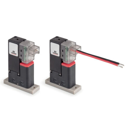
3/2-way – Normally Closed (NC) and Normally Open (NO)
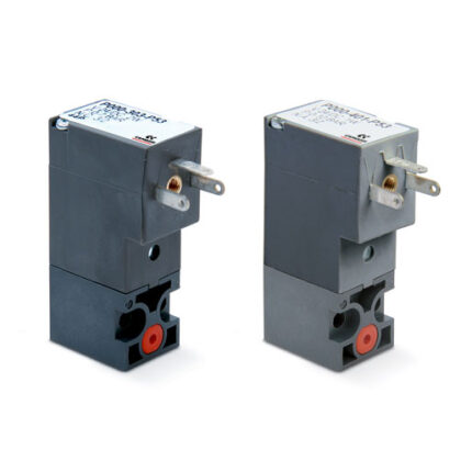
Series W directly operated solenoid valves are available as 3/2-way either NC or NO.
Both versions can be mounted on single sub-bases or manifolds and they are equipped with a monostable manual override.
Filtered air class [5:4:4] according to ISO 8573-1:2010 (max oil viscosity 32 cSt), inert gas
Response time when discharging (ISO 12238)
ON <10 ms – OFF <15 ms
Manual override
Monostable
Installation
In any position
MATERIALS IN CONTACT WITH THE MEDIUM
Body
PBT
Seals
PU – NBR – FKM – EPDM
Internal parts
Stainless steel
ELECTRICAL FEATURES
Voltage
12 … 48 V DC – Other voltages on demand
Voltage tolerance
±10%
Power consumption
2 W – 1 W (24 V DC only)
Duty cycle
ED 100%
Electrical connection
Connector DIN EN 175 301-803-C (8 mm) – 300 mm flying leads
Protection class
IP65 with connector
Special versions available on demand.
Coding Example
W
0
00
–
3
0
3
–
W
2
3
W
SERIES
0
BODY DESIGN
0 = single sub-base (only M5) or interface
1 = single manifold
2 = double manifold
00
NUMBER OF POSITIONS
00 = ISO 15218 interface
01 = single base (M5 only)
02 ÷ 99 = manifold number of positions
3
NUMBER OF WAYS – FUNCTIONS
0 = manifold or single sub-base
3 = 3/2-way – NC
4 = 3/2-way – NO
5 = 3/2-way – NC electric part revolved by 180°
6 = 3/2-way – NO electric part revolved by 180°
0
VALVE PORTS
0 = ISO 15218 interface
MANIFOLD PORTS for P – PL – PN – W Series
2 = M5 thread – front outlets
3 = tube Ø 3 mm fittings – front outlets
4 = tube Ø 4 mm fittings – front outlets
6 = M5 thread – bottom outlets
7 = tube Ø 3 mm fittings – bottom outlets
8 = tube Ø 4 mm fittings – bottom outlets
3
ORIFICE DIAMETER
1 = Ø 0.8 mm
3 = Ø 1.5 mm
5 = Ø 1.1 mm – NC versions
6 = Ø 1.5 mm – NC versions with voltage tolerance -25% ÷ +10%
5 = Ø 0.9 mm – NO versions
W
MATERIALS
E = PBT body – EPDM seals
F = PBT body – FKM seals
W = PBT body – NBR – FKM – PU seals
2
ELECTRICAL CONNECTION
1 = 300 mm flying leads
2 = DIN EN 175 301-803-C (8 mm)
3
VOLTAGE – POWER CONSUMPTION
2 = 12 V DC – 2 W
3 = 24 V DC – 1 W – NC Ø 0.8 mm version only
3 = 24 V DC – 2 W
4 = 48 V DC – 2 W
FIXING
= fixing screws for metal
P = fixing screws for plastic
USE WITH OXYGEN:
= Not suitable for use with oxygen
OX1 = for use with oxygen – cleanliness level according to ASTM G93-03 Standard Level E
OX2 = for use with oxygen – cleanliness level according to ASTM G93-03 Standard Level B)