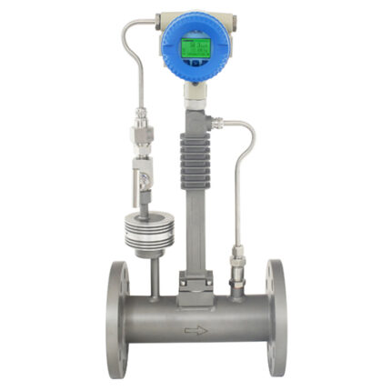
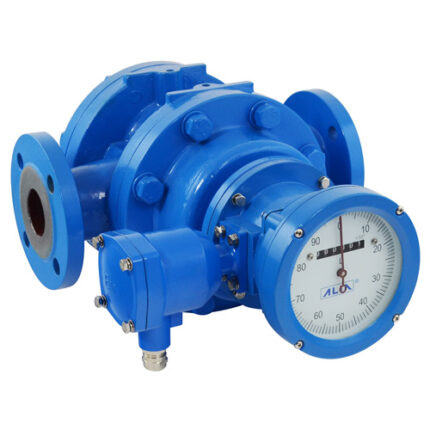
Features
- Designed for a wide range of liquid applications
- High measuring accuracy, regardless of the mounting position
- 4-20 mA with HART signal and pulse outputs, user selectable
- Abrasion-resistant tungsten carbide rotor shaft and bearings
- Superior materials of construction for high performance in aggressive environments
- Easily cleaned and designed to flush particulates through the turbine with the medium
- For variable use thanks to different pick-up sensors as well as a variety of connections and sizes
Specification
| Size | : | 6, 10, 15, 20, 25, 32, 40, 50, 65, 80, |
| 100, 125, 150, 200 mm | ||
| Measuring Medium | : | Liquid |
| Max. Viscosity | : | 1-60 cSt |
| Measuring Range | : | 0.1-800 m3/hr |
| Accuracy | : | +/-1.0% of reading (Standrad) |
| : | +/-0.5% of reading (Option) | |
| Repeatability | : | +/-0.2% of reading |
| Pressure Drop | : | Max. 290 mbar at 100% Measuring range |
| (Density 1 g/cm3, Viscosity 1cp) | ||
| Unit | : | m3/d, m3/hr, m3/m, m3/s, l/hr, l/m, l/s, |
| t/d, t/hr, t/m, kg/d, kg/hr, kg/m, kg/s, | ||
| g/hr, g/m, g/s, USG/m, UKG/m, bbl/d, lb/hr… | ||
| Material | ||
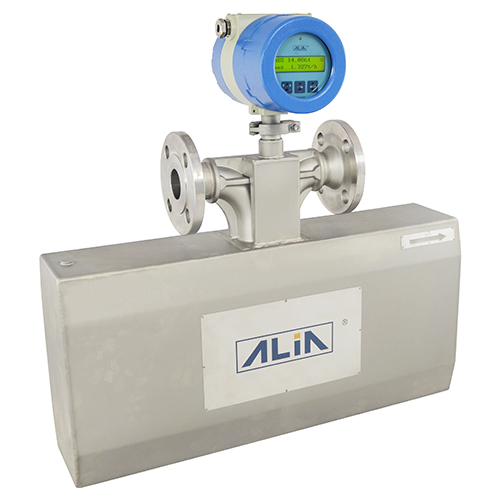
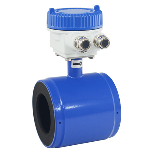
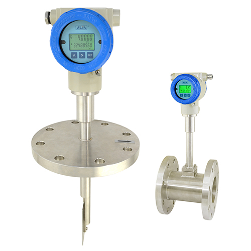
| Body | : | S.S. 304 / S.S. 316 |
| Bearing | : | Tungsten nickel alloy |
| Rotor | : | S.S. 420 / S.S. 2205 |
| Housing | : | Aluminum Alloy |
| Angular Connecto | : | PA66 |
| Process Connection | : | Flange (DN6 – DN200) |
| : | Thread (DN6 – DN50) | |
| : | Tri-Clamp (DN15 – DN80) | |
| Max. Pressure | : | Flange: 63 kgf/cm2 |
| : | Thread: 63 kgf/cm2 | |
| : | Tri-Clamp: 10 kgf/cm2 |
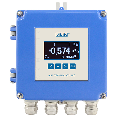
| Local Display | : | 2 or 3 lines LCD |
| : | 6 Digits flowrate | |
| : | 8 Digits totalizer | |
| Operation Temperature | : | -20~120 °C(Without Display: -20~70 °C) |
| Ambient Temperature | : | -20~60 °C |
| Current Output | : | 4-20 mA (2 wires) |
| Load | : | Rohm=(VDC-18) * 50 |
| Pulse Output | : | Scaled Pulse / Unscaled Pulse |
| Load | : | 1000-5000 Ω |
| Communication | : | HART (Compatible) |
| : | RS485 (MODBUS Protocol) | |
| Data Storage | : | Operation parameter and totalizer figures |
| are stored by EEPROM (>10 years) | ||
| Cable Entry | : | Standard: M20 Option: 1/2″ NPTF |
| : | Angular Connector DIN EN 175301-803 A | |
| Angular Connector | ||
| Ingress Protection | : | IP65 |
| Wire Cross-section | : | Max. 1.5 mm2 |
| Cable Diameter | : | 6-8 mm |
| Power Supply | : | 18-32 VDC / 18-26 VDC (without display) |
| : | Ni-MH Battery (3 years working hours) | |
| Protection Class | : | IP65 (Angular Connector) |
| : | IP67 (Aluminum Alloy Housing) | |
| : | Explosion Proof, Ex d IIC T6 |