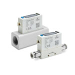
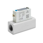
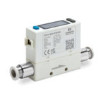
Flow sensors Series FS
Sizes: 17, 30, 35
The Series FS is available for flows ranging from 0.5 to 2000 L/min, offered in three different sizes, also available with the pressure sensor version included.
The display is designed to be rotatable, thus allowing for easy reading of the monitored values.
The cumulative flow rate is immediately visible on the display.Main features:
The display is designed to be rotatable, thus allowing for easy reading of the monitored values.
The cumulative flow rate is immediately visible on the display.Main features:
- Real-time monitoring: Allows for constant flow control at all times.
- Wide range of applications: Suitable for multiple uses, from small workshops to large industries.
- Painting robots: Ideal for managing the airflow in painting processes, contributing to the economization of technical gases.
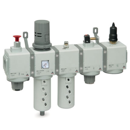
Categories: Air treatment, CAMOZZI, Flow sensors
General Data
| Mod. | FS (Flow sensors) | FSP (Flow sensor + Pressure sensor) |
| Sizes | 01 (17 mm) 02 (30 mm) 03 (35 mm) | |
| Medium | Dry air, N2, Non-corrosive / Non-flammable gas | |
| Measured flow rates | FS01 – FSP01 (0 ÷ 1 to 0 ÷ 200 L/min) FS02 – FSP02 (2 ÷ 500 to 10 ÷ 1000 L/min) FS03 – FSP03 (10 ÷ 2000 L/min) | |
| Flow direction | Unidirectional | |
| Rated pressure range [bar] | Not applicable | -0,90 ÷ 10 Bar |
| Display | 4 digital * 4 digital, 7 segment screen ( Red / Green / Orange ) | |
| Instant flow range | FS01 – FSP01 (0 ÷ 1,050 to 0 ÷ 210 L/min) FS02 – FSP02 (0 ÷ 525 to 0 ÷ 1050 L/min) FS03 – FSP03 (0 ÷ 2100 L/min) | |
| Instant flow rate display LPM (Liters per minute) | FS01 – FSP01 (1 mL/min to 1 L/min) FS02 – FSP02, FS03 – FSP03 (1 L/min) | |
| Instant flow rate display CFM (Cubic feet / minute) | FS01 – FSP01 (0.01 ft3/min to 1 ft3/min) FS02 – FSP02, FS03 – FSP03 (1 ft3/min) | |
| Accumulated flow displayed (LPM or CFM) | FS01 – FSP01 (99999999 mL to 9999999.9 L) FS02 – FSP02, FS03 – FSP03 (99999999 L) | |
| Min. value display LPM or CFM | FS01 – FSP01 (1 mL to 1 L) (0.1 ft3 to 1 ft3) FS02 – FSP02, FS03 – FSP03 (1 L) (1 ft3) | |
| Display range | Not applicable | -1 ÷ 10 bar |
| Min. setting scale [kPA] | Not applicable | 1 |
| Min. setting scale [kfg/cm2] | Not applicable | 0.01 |
| Min. setting scale [bar] | Not applicable | 0.01 |
| Min. setting scale [psi] | Not applicable | 0.1 |
| Guaranteed range of flow display | 2 ÷ 100 % F.S. | |
| Accuracy of flow display indicators | FS01 – FSP01 (± 3% F.S. ± 1 digit)*1 FS02 – FSP02, FS03 – FSP03 (± 3% F.S. ± 1 digit)*5 | |
| Analog output accuracy of the flow display | FS01, FSP01 (± 5% F.S.)*1 FS02 – FSP02, FS03 – FSP03 (± 5% F.S.)*5 | |
| Repeatability of flow visualization | FS01 – FSP01 (±1% F.S. ±1 digit)*2 FS02 – FSP02, FS03 – FSP03 (±1% F.S. ±1 digit)*2, (± 2% F.S. when the response time is set to 50 ms)*2 | |
| Linearity of flow visualization | ± 3% F.S. *2 | |
| Variation with temperature of the flow display | FS01 – FSP01 ± 2% F.S. (15 ÷ 35°C); ± 5% F.S. (0 ÷ 15°, 35 ÷ 50°C), (compared with *2) FS02 – FSP02, FS03 – FSP03 ± 5% F.S. (compared with *2) | |
| Variation with pressure | FS01 – FSP01 (± 5% F.S. ± 1 digit)*3 FS02 – FSP02, FS03 – FSP03 (± 5% F.S. ± 1 digit)*6 | |
| Guaranteed range pressure accuracy | Not applicable | 0 ÷ 100 % F.S. |
| Indicators accuracy | Not applicable | ± 2% F.S. ± 1 digit *7 |
| Analog output accuracy | Not applicable | ± 2.5% F.S. *7 |
| Repeatability pressure accuracy | Not applicable | ± 0.2% F.S. ± 1 digit *7 |
| Linearity pressure accuracy | Not applicable | ± 1% F.S. *7 |
| Variation with temperature precision pressure | Not applicable | ± 2% F.S. (compared with *7) |
| General digital output | 2 | |
| Digital output flow response time | 800 ms (available 50, 80, 120, 200, 400, 1500 ms) | |
| Response time to digital output pressure | Not applicable | 2.5 ms (available 25, 100, 250, 500, 1000, 1500 ms) |
| Digital flow output mod | Hysteresis Mode, Window Comparator Mode, Accumulated Output, Accumulated Pulse Output | |
| Digital pressure output | Not applicable | |
| Hysteresis | Adjustable | |
| Short circuit protection | Yes | |
| Accumulated pulse output | FS01 – FSP01 (10 mL/impulse to 2 L/impulse) FS02 – FSP02 (5 L/impulse to 10 L/impulse) FS03 – FSP03 (10 L/impulse) | |
| Analog voltage output | 1 ÷ 5 V – Output Impedance: 1 kΩ | 1 ÷ 5 V; *8 – Output Impedance: 1 kΩ |
| Analog current output | 4 ÷ 20 mA – Load Impedance: ≤ 300 Ω | 4 ÷ 20 mA; *8 – Load Impedance: ≤ 300 Ω |
| Response time | ≤ 100 ms | Pressure: ≤ 50 ms; Flow: ≤ 100 ms |
| External input | Input Open collector, ≤ 0.4V, ≥ 30 ms | |
| Communication interface | RS-485 *7 | |
| Power supply voltage | 12 ÷ 24V DC ± 10 % – Ripple (P-P) ≤ 10 % | |
| Current consumption | ≤ 50 mA | |
| Operating pressure | FS01 – FSP01 (-0,9 ÷ 8 bar) FS02 – FSP02, FS03 – FSP03 (0 ÷ 10 bar) | |
| Withstand pressure [bar] | Not applicable | FSP01 (10 bar) FSP02, FSP03 (15 bar) |
| Protection class | IP40 | |
| Working fluid temperature | 0 ÷ 50 °C (no condensation or freezing) | |
| Environmental temperature | Operation: 0 ÷ 50 °C ; Storage: -10 ÷ 60 °C (no condensation or freezing) | |
| Environmental humidity | Operation / Storage: 35 ÷ 85 % R.H. (no condensation) | |
| Insulation resistance | ≥ 50 MΩ (500 V DC, between case and lead wire) | FSP01 (≥ 2 MΩ – 50 VDC, between case and lead wire) FSP02, FSP03 (≥ 50 MΩ – 500 VDC, between case and lead wire) |
| Maximum Voltage | 1000 VAC for 1 minut, between case and lead wire | FSP01 (250 VAC for 1 minut, between case and lead wire) FSP02, FSP03 (1000 VAC for 1 minut, between case and lead wire) |
| Vibration | Total amplitude 1.5 mm or 10 G, 10 Hz ÷ 55 Hz ÷ 10 Hz scan for 1 minute, 2 hours each direction of X, Y and Z | |
| Shock | 100 m/s2 (10 G), 3 times each in direction of X, Y and Z | |
| EMC | IEC 61000-6-2; IEC 61000-6-4 | |
| Lead wire | Ø4 Oil-resistance cable (PVC) – 26 AWG (0.15 mm2) – 6 cores | |
| Port sizes | FS01 – FSP01 (Ø6 to Ø8) FS02 – FSP02 (Rc1/2, G1/2) FS03 – FSP03 (Rc3/2, G3/4) | |
| Weight (with 2 meter lead wire) | FS01 – FSP01 (109.3 g to 112.7 g approx.) FS02 – FSP02 (250 g to 325 g) FS03 – FSP03 (325 g) | |
Coding Example
| FS | 01 | – | 201 | – | 031 | – | R8 |
| FS | SERIES FS = Flow sensor FSP = Flow sensor + Pressure sensor |
| 01 | SIZE 01 = 17 mm 02 = 30 mm 03 = 35 mm |
| 201 | FLOW RATE RANGE 005 = 500 mL/mil (only size 01) – Available on request 010 = 1000 mL/min (only size 01) 050 = 5 L/min (only size 01) – Available on request 100 = 10 L/min (only size 01) – Available on request 500 = 50 L/min (only size 01) 101 = 100 L/min (only size 01) – Available on request 201 = 200 L/min (only size 01) 501 = 500 L/min (only size 02) 102 = 1000 L/min (only size 02) 202 = 2000 L/min (only size 03) |
| 031 | OUTPUT SPECIFICATIONS 010 = 2 NPN output + Analog output 1 – 5 V 011 = 2 NPN output + Analog output 4 – 20 mA 020 = 2 NPN output + RS485 – Available on request 030 = 2 PNP output + Analog output 1 – 5 V 031 = 2 PNP output + Analog output 4 – 20 mA 040 = 2 PNP output + RS485 – Available on request |
| R8 | PORT SIZE R6 = Ø6 mm for Flow Rate type 005, 010, 050, 100, 500 R8 = Ø8 mm for Flow Rate type 101, 201 F9C = G1/2 for Flow Rate Range 501/102 F12C = G3/4 for Flow Rate Range 202 |