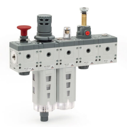
Assembled FRL Series MX
Assembly through rapid clamps
The FRL groups Series MX are also available in the already mounted version (with a single code).
The use of three different types of rapid clamps (standard, with wall fixing screws or with brackets) allows an easy mounting of the assembled groups and to carry out maintenance operations on the single components with no need to disassemble the group.
General Data
| Construction | Modular, compact |
| Materials | See catalogue pages referring to the single component |
| Ports | MX2: G3/8 – G1/2 – G3/4 MX3: G3/4 – G1 |
| Mounting | Vertical in-line Wall-mounting (by means of clamps) Panel mounting |
| Operating temperature | -5°C ÷ 50°C up to 16 bar (according to the single component characteristics) -5°C ÷ 60°C up to 10 bar (according to the single component characteristics) |
Coding Example
| MX | 2 | – | 3/8 | – | V01 | X | F00 | X | V1841AB | – | KK | – | LH |
| MX | SERIES | |||
| 2 | (1) | SIZES 2 = G3/8 – G1/2 – G3/4 3 = G3/4 – G1 | ||
| 3/8 | (2) | IN / OUT THREADS 3/8 = G3/8 1/2 = G1/2 3/4 = G3/4 1 = G1 | ||
| V01 | (3) | MODULE + [+] (to configure the modules, see the single components pages): | F…= Filter | V… = Lockable isolation valve |
| [ * ] | The following ACCESSORIES can be added after every single module: REGULATOR AND FILTER-REGULATOR MX2 | REGULATOR AND FILTER-REGULATOR MX3 | ||
| LOCKABLE ISOLATION VALVE MX2 +A30 = 2901 1/2’’ (Silencier) +A31 = 2921 1/2’’ (Silencier) +A32 = 2931 1/2’’ (Silencier) +A33 = 2928 1/2’’ (Silencier) | LOCKABLE ISOLATION VALVE MX3 +A34 = 2901 3/4’’ (Silencier) +A35 = 2921 3/4’’ (Silencier) +A36 = 2931 3/4’’ (Silencier) +A37 = 2928 3/4’’ (Silencier) | |||
| SOFT START VALVE +A00 = PM11-NA (Pressure switch, normally open) +A01 = PM11-NC (Pressure switch, normally closed) +A04 = PM11-SC (Pressure switch) +A05 = PM681-1 (Pressure switch) +A18 = PM681-3 (Pressure switch) | ||||
| TAKE-OFF BLOCK MX2 +A11 = PM681-1 (Pressure switch) +A24 = PM681-3 (Pressure switch) +A08 = PM11-NA (normally open pressure switch) with fitting for fixing to the module +A09 = PM11-NC (normally closed pressure switch) with fitting for fixing to the module +A03 = PM11-SC with fitting for fixing to the module Example: MX2-3/8-V01+A32XF00-KK-LH | TAKE-OFF BLOCK MX3 +A06 = PM11-NA (normally open pressure switch) with fitting for fixing to the module +A07 = PM11-NC (normally closed pressure switch) with fitting for fixing to the module +A10 = PM681-1 (Pressure switch) +A25 = PM681+3 (Pressure switch) +A02 = PM11-SC with fitting for fixing to the module Example: MX3-3/4-V01+A36XF00-KK-LH | ISOLATION VALVE MX2 / MX3 +A40 = U7H Coil UL (12V DC) +A41 = U77 Coil UL (24V DC) +A42 = U79 Coil UL (48V DC) +A43 = U7K Coil UL (110V AC) +A44 = U7J Coil UL (230V AC) +A45 = G7H Coil (12V DC) +A46 = G77 Coil (24V DC) +A47 = G79 Coil (48V DC) +A48 = G7K Coil (110V AC) +A49 = G7J Coil (230V AC) | ||
| X | (4) | MODULES CONNECTION (according to the positioning scheme on the following page): X = Rapid clamp kit Z = Rapid clamp kit with wall fixing screw Y = Rapid clamp kit with wall fixing brackets | ||
| F00 | (5) + [ * ] | see MODULE (3) | ||
| X | (4) | |||
| V1841AB | (5) + [ * ] | see FORM (3) – if other forms are present | ||
| KK | (6) | TERMINAL CONNECTIONS + [ ** ] = no terminal connection HH = n° 1 rapid clamp kit with flanges (IN / OUT) JJ = n° 1 rapid clamp kit with wall fixing screws + flanges (IN / OUT) KK = n° 1 rapid clamp kit with wall fixing brackets + flanges (IN / OUT) | ||
| [ ** ] | WALL CONNECTION: REGULATOR and FILTER-REGULATOR S = Bracket (only with clamps mod. X o HH) Codes examples: MX3-1-R..XV..-S ; MX3-1-R..XV..-HSH | |||
| LH | (7) | FLOW DIRECTION: = from left to right (standard) LH = from right to left | ||
| (4) + (5) + [ * ] | REPEATABLE COMBINATION for a “n” number of times |
| MX | 2 | – | 3/8 | – | 000001 |
| MX | SERIES |
| 2 | SIZE 2 = G3/8 – G1/2 – G3/4 3 = G3/4 – G1 |
| 3/8 | PORTS: 3/8 = G3/8 1/2 = G1/2 3/4 = G3/4 1 = G1 |
| 000001 | GROUP COMPOSITION: 000001 = F10 + R004 + L00 000002 = FR1004 + L00 000003 = V01 + FR1004 + L00 000004 = V01 + FR1004 000005 = FR1004 + V16 + AV 000006 = FR1004 + L00 + V16 + AV 000007 = V01 + FR1004 + V16 + AV 000008 = V01 + FR1004 + L00 + V16 + AV + PRESS. NO 000009 = V01 + FR1004 + L00 + V16 + AV + PRESS. NC 000010 = V01 + FR1004 + V16 + AV + PRESS. NO 000011 = V01 + FR1004 + V16 + AV + PRESS. NC 000012 = F13 + FC03 |
| WARNING: IN THE PRESENCE OF METAL PIPES, THE USE OF CONNECTION FLANGES MAKE THE MAINTENANCE ACTIVITIES EASIER. |