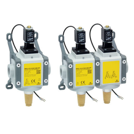
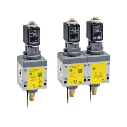
3/2-way quick exhaust safety valves with soft start valve Series MX SAFEMAX
Ports: G1/2
In this configuration, in addition to the characteristics of the versions with solenoid valves only, the soft start function has been integrated, which allows a gradual introduction of pressure into the system.
Its positioning upstream of the solenoid valves allows, even in the event of an anomaly, to always have the maximum discharge flow rate. Thanks to the internal construction solutions it was possible to maintain the design and dimensions of the standard product, no further interface plates are necessary.
Please note: the safety valve alone is not sufficient to guarantee the safety function. Its activation requires the use of a supervisor device.
The Machinery Directive (MD) 2006/42 / EC establishes the safety requirements that a machine must respect in order to protect the health of people during its use. Series MX SAFEMAX solenoid valves comply with ISO 13849-1, regarding the safe design of control systems that perform safety functions.
Categories: Air treatment, CAMOZZI, Safety valves
General Data
| Construction | Modular, compact, spool-type |
| Ports | G1/2 |
| Mounting | In-line, wall-mounting (by means of clamps) |
| Working temperature | -5 ÷ +60 °C |
| Working pressure | With internal servo-pilot: 3,5 bar ÷ 10 bar With external servo-pilot: 0,5 bar ÷ 10 bar (pilot 3,5 bar ÷ 10 bar, greater or equal to operating P) |
| Flow rate (6 bar) | Single version: 1→2 = 4100 Nl/min (ΔP 1) 2→3 = 5000 Nl/min (free flow) Double version: 1→2 = 3300 Nl/min (ΔP 1) 2→3 = 5000 Nl/min (free flow) |
| Medium | Filtered air in class [7:4:4] according to ISO 8573-1. In case lubricated air is used, we recommend ISOVG32 oil and to never interrupt lubrication |
| COIL SPECIFICATIONS | |
| Connection | DIN EN 175 301-803-B |
| Voltage | 24V DC (±10%) 3,1W (ED 100%) |
| SENSOR SPECIFICATIONS | |
| Connection | With wires, M8 |
| Voltage | 10-28V DC |
| Operation | Magnetoresistive |
| Contact | N.O. PNP, ON signal with sol. valve in NC position |
| Max current | EX version: 200 mA 0,65 W UL version: 100 mA 3 W CE version: 200 mA 5,5 W |
| COMPLIANCE WITH EN ISO 13849-1 STANDARD | |
| Performance level reachable (PL) | Single version: category 2, PLd Double version: category 4, PLe |
| B10d | 2.000.000 cycles |
Coding Example
| MX | 2 | – | 1/2 | – | V | 18 | 2 | 0 | A | B | – | KK | – | LH |
| MX | SERIES |
| 2 | SIZE |
| 1/2 | PORT 1/2 = G1/2 |
| V | COMPONENT V = 3/2-way valve |
| 18 | CONSTRUCTION 18 = Internal servo-pilot with soft start valve 19 = External servo-pilot with soft start valve |
| 2 | CHANNEL 2 = Single |
| 0 | ACCESSORIES 0 = Without silencer 1 = With silencer |
| A | SENSOR A = UL sensor, 2 mt cable B = UL sensor, 5 mt cable C = ATEX sensor, 2 mt cable D = ATEX sensor, 5 mt cable E = CE sensor M8 connector, 300 mm cable |
| B | VERSION A = Atex B = UL C = CE Sensor and version must comply with the same Standard / directive AB, BB – CA, DA – EC |
| KK | MOUNTING = Without mounting accessories Z = Central wall clamps Y= Central wall brackets HH = Side quick clamps and flanges JJ= Side wall clamps and flanges KK = Side wall brackets and flanges |
| LH | FLOW DIRECTION = From left to right (standard) LH = From right to left |
Coding Example double valve
| MX | 2 | – | 1/2 | – | V | 18 | 4 | 0 | A | B | – | KK | – | LH |
| MX | SERIES |
| 2 | SIZE |
| 1/2 | PORT 1/2 = G1/2 |
| V | COMPONENT V = 3/2 way valve |
| 18 | CONSTRUCTION 18 = Internal servo-pilot with soft start valve 19 = External servo-pilot with soft start valve |
| 4 | CHANNEL 4 = Double |
| 0 | ACCESSORIES 0 = Without silencer 1 = With silencer |
| A | SENSOR A = UL sensor, 2 mt cable B = UL sensor, 5 mt cable C = ATEX sensor, 2 mt cable D = ATEX sensor, 5 mt cable E = CE sensor M8 connector, 300 mm cable |
| B | VERSION A = Atex B = UL C = CE Sensor and version must comply with the same Standard / directive AB, BB – CA, DA – EC |
| KK | MOUNTING = Without mounting accessories Z = Central wall clamps Y= Central wall brackets HH = Side quick clamps and flanges JJ= Side wall clamps and flanges KK = Side wall brackets and flanges |
| LH | FLOW DIRECTION = From left to right (standard) LH = From right to left |
Download
Instruction sheets
Software