Filter-regulators Series MX
MX2 ports: G3/8, G1/2, G3/4 – MX3 ports: G3/4, G1
Modular
Bowl with technopolymer cover and bayonet-type mounting
Modular
Bowl with technopolymer cover and bayonet-type mounting
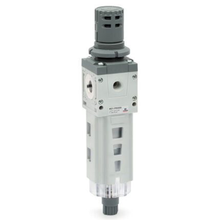
Series MX filter-regulators integrate filter and pressure reducer in one unit.
They are, therefore, compact and suitable for pre-filtering functions.
Available with or without draining (relieving), they are equipped with a valve diaphragm for a direct pressure regulation and with an integrated condensate drainer, manual or automatic.
Moreover, they are equipped with a built-in pressure gauge.
The Series MX has been realized to offer a multi-sector solution that guarantees saving in terms of installation time, space and costs.
Categories: Air treatment, CAMOZZI, Pressure filter-regulators
General Data
| Construction | Modular, compact with filtering element in HDPE |
| Materials | See TABLE OF MATERIALS on the following page |
| Ports | MX2: G3/8 – G1/2 – G3/4 – MX3: G3/4 – G1 |
| Condensate capacity | MX2: 55 cc – MX3: 85 cc |
| Mounting | Vertical in-line, wall-mounting (by means of clamps), panel mounting |
| Operating temperature | 0,3 ÷ 16 bar / -5°C ÷ 50°C (with the dew point of the fluid lower than 2°C at the min. working temperature) 0,3 ÷ 10 bar / -5°C ÷ 60°C (with the dew point of the fluid lower than 2°C at the min. working temperature) |
| Quality of delivered air according to ISO 8573-1:2010 | Class [6:8:4] with 5 μm filtering element Class [7:8:4] with 25 μm filtering element |
| Draining of condensate | MX2: manual-semi automatic (standard), automatic, depressurization protected, direct G1/8 exhaust MX3: manual-semi automatic (standard), automatic, direct G1/8 exhaust |
| Exit pressure | 0,5 ÷ 10 bar (standard), 0,5 ÷ 4 bar and 0,5 ÷ 7 bar |
| Nominal flow | See FLOW DIAGRAMS on the following page |
| Fluid | Compressed air |
Coding Example
| MX | 2 | – | 1/2 | – | FR | 0 | 0 | 0 | 4 | – | LH |
| MX | SERIES |
| 2 | SIZE 2 = G3/8 – G1/2 – G3/4 3 = G3/4 – G1 |
| 1/2 | PORT 3/8 = G3/8 1/2 = G1/2 3/4 = G3/4 1 = G1 |
| FR | FILTER-REGULATOR |
| 0 | FILTERING ELEMENT WITH DESIGN TYPE: 0 = 25 µm with relieving (standard) 1 = 5 µm with relieving 2 = 25 µm without relieving (with semiautomatic-manual drain only) 3 = 5 µm without relieving (with semiautomatic-manual drain only) 4 = 25 µm with relieving and by-pass valve 5 = 5 µm with relieving and by-pass valve 6 = 25 µm without relieving, with by-pass valve 7 = 5 µm without relieving, with by-pass valve |
| 0 | DRAINING OF CONDENSATE (further details in the dedicated section) 0 = semiautomatic-manual drain 3 = automatic drain 5 = depressuring drain, protected 8 = without drain, with port G1/8 |
| 0 | OPERATING PRESSURE 0 = 0,5 ÷ 10 bar (standard) 4 = 0,5 ÷ 4 bar 7 = 0,5 ÷ 7 bar (MX2 only) |
| 4 | PRESSURE GAUGE 0 = without pressure gauge (with threaded port) 2 = with built-in pressure gauge 0-6 and working pressure 0,5 ÷ 4 bar 3 = with built-in pressure gauge 0-10 and working pressure 0,5 ÷ 7 bar (MX2 only) 4 = with built-in pressure gauge 0-12 and working pressure 0,5 ÷ 10 bar (standard) |
| LH | FLOW DIRECTION = from left to right (standard) LH = from right to left |
For the assembly of a single component with fixing flanges or wall-mounting, see the section “FRL Series MX Assembled”
