Rodless cylinders Series 50
Double-acting, magnetic, cushioned
ø 16, 25, 32, 40, 50, 63, 80 mm
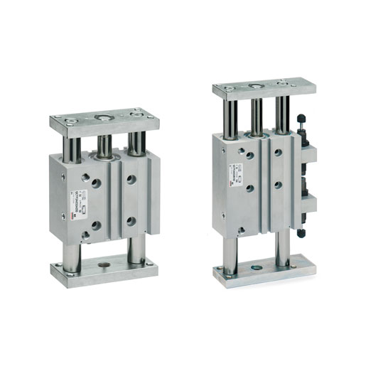
Series 50 rodless cylinders are available in 7 different diameters to cover as many applications as possible.
A permanent magnet is assembled on the cylinder piston allowing the position to be detected by means of proximity switches positioned on the sliding axis.
This series of cylinder is normally supplied with end-stroke cushioning, that can be regulated by means of a screw located on the end-cover.The Series 50 cylinders are recommended to be used according to the load values and torque forces detailed in the relative tables.
Categories: CAMOZZI, Pneumatic Actuation, Rodless cylinders
General Data
| Type of construction | Rodless with integral carriage |
| Operation | Double-acting |
| Materials | End-covers, piston and barrel = AL seals = PU and NBR |
| Operating temperature | 0°C ÷ 50°C(with dry air – 10°C) |
| Operating pressure | 1 ÷ 8 bar |
| Speed | 10 ÷ 1000 mm/sec (without load) |
| Fluid | Clean air, without lubrication. If lubricated air is used, it is recommended to use oil ISOVG32. Once applied the lubrication should never be interrupted. |
| Strokes min – max | For all bores 100 ÷ 4000 mm |
| Stroke tolerance | Strokes ≤ 1000 mm = 0 / +0,6 mm strokes > 1000 mm = 0 / +3 mm |
| Type of mounting | Foot mounted |
Coding Example
| 50 | M | 2 | P | 50 | A | 0500 |
| 50 | SERIES | |
| M | VERSION M = standard magnetic | |
| 2 | OPERATION 2 = double-acting cushioned | PNEUMATIC SYMBOL CDSS (see the following pages) |
| P | MATERIALS P = anodized AL profile tube – PU and NBR seals – standard carriage U = anodized AL profile tube – PU and NBR seals – flanged carriage | |
| 50 | BORE 16 = 16 mm 25 = 25 mm 32 = 32 mm 40 = 40 mm 50 = 50 mm 63 = 63 mm 80 = 80 mm | |
| A | TYPE OF MOUNTING A = standard | |
| 0500 | STROKE (see table) |
