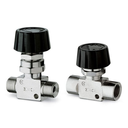
The unidirectional flow controllers are equipped with M5, G1/8, G1/4, G3/8 and G1/2 ports.
G1/8 and G1/4 ports are available with two different types of adjustment, whereas M5, G3/8 and G1/2 ports have just one type of adjustment.
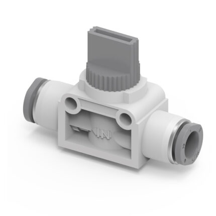
All models can be panel or wall mounted or they can be mounted on cylinders, as required.To choose the most suitable model, it is recommended to:
- Calculate the quantity of air in Nl/min
- Determine the stroke time of the cylinder
- Check the flow diagrams.