Compact cylinders Series 31

Double and single-acting, double-acting non-rotating, magnetic
Ø 12, 16, 20, 25 mm
Ø 32, 40, 50, 63, 80, 100 mm UNITOP
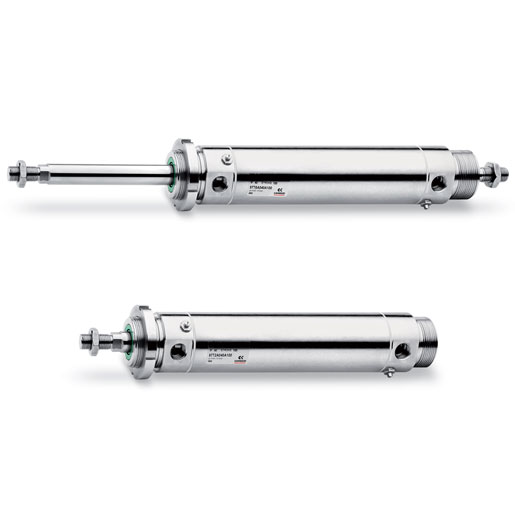
The compact dimensions allow Series 31 single and double-acting magnetic cylinders to be installed within confined spaces.
These cylinders are suitable for use with feet, brackets.These cylinders are available in 10 different bore sizes from Ø12 to Ø100.
The guides are inserted in the external profile parallel to the sliding axis on three sides.
These guides are used to locate the switches that sense the piston position.
The construction design of these cylinders provides excellent axis stability.
They are available either with a male or female thread.
These cylinders can be supplied in W version for high temperatures (140°C).
This last version is not magnetic.

General Data

Type of constructioncompact profile
Operationsingle and double-acting
MaterialsAL body and end-blocks – rolled stainless steel AISI 303 rod – AL piston rod
PU seals or FKM seals for high temperatures (140°C)
Bracketsflange, feet, trunnion
Stroke min – maxSeries 31R, 31M and 31F: Ø12÷25 = 1÷200mm, Ø32 ÷ 63 = 1÷300 mm, Ø80÷100 = 1÷400mm
The min. stroke for the use of sensors is 10 mm.
Single-acting = 5÷25 mm (see the table of standard strokes)
Operating temperature0°C ÷ 80°C (with dry air – 20°C)
Operating pressure1 ÷ 10 bar (double-acting); 2 ÷ 10 bar (single-acting)
Fluidfiltered air, without lubrication. If lubricated air is used, it is recommended to use oil ISOVG32. Once applied the lubrication should never be interrupted.
Speed10 ÷ 1000 mm/sec (without load)

Coding Example

31M2A032A050
31SERIES
31 = compact magnetic
MVERSION
M = male rod thread, mounted with rod nut Mod. U
F = female rod thread
R = non-rotating with flange only double-acting
2OPERATION
1 = single-acting, front spring
2 = double-acting
3 = double-acting, through-rod
4 = single-acting, rear spring
7 = single-acting, through-rod
PNEUMATIC SYMBOLS
CS06
CD08 (Only for version M and F) – CD25 (Only for version R)
CD12 (Only for version M and F) – CD25 (Only for version R)
CS08
CS10
AMATERIALS
A = rolled stainless steel AISI 303 rod – AL tube profile
032BORE
012 = 12 mm
016 = 16 mm
020 = 20 mm
025 = 25 mm
032 = 32 mm
040 = 40 mm
050 = 50 mm
063 = 63 mm
080 = 80 mm
100 = 100 mm
ADESIGN TYPE
A = standard
050STROKE (see the table)
= standard
V = rod seal FKM
W = seals in FKM for high temperatures (140°C),
only available in the double-acting, non magnetic version

Download

– REACH-Series-31.pdf
– RoHS-Series-31.pdf
– Series_31_cylinders.pdf

Instruction sheets

– EX_Instruction_FI-CIL_ATEX_93-7550-0001_revG.pdf